
Bailey Bridges played a critical role in WW2 at the tactical and operational levels. They enabled manoeuvre over obstacles where previously a river had denied it. Bought about by the requirements to bridge faster, across wider lengths and to carry heavier loads, it often enabled the striking of strengths against weaknesses by enabling troops to cross a river where they were not expected. From design to their first combat use was just 10 months, and over 200 miles of fixed bridges and 40 miles of floating where produced.
The story of the Bailey Bridge in WW2 highlights the massive contribution of military engineering to the winning of the war. Admiral William F Halsey identified four technologies that he thought played a crucial role in victory – submarines, radar, aircraft and bulldozers. We have forgotten the legacy of military engineering and what it does, but more importantly what it enables in theatre. We must remember and rebuild those LSCO skills. As a start – here is an article originally published in the March 1946 Edition of The Military Engineer.
JOHN A. THIERRY
Captain, Corps of Engineers
To the bridge engineer, World War II has been a war of prefabricated portable bridges designed for rapid erection close behind assault troops. Both Allied and enemy armies have developed all types of prefabricated fixed, floating, and suspension bridges for foot, vehicular, and even railway traffic.
Of the multitude of designs adopted, the Bailey bridge, named after its British inventor Mr. Donald Colman Bailey, proved to be the most significant. Throughout the war, it was the principal tactical fixed bridge of the Allied armies. It also served as the standard floating bridge of the British Army. Originally designed as a fixed bridge for single-lane vehicular traffic, it was adapted successfully to a multitude of other uses and became the first all-purpose military bridge. It was unequalled in speed and simplicity of erection, economy of construction over a great range of spans and capacities, and adaptability to widely different site conditions. The Bailey bridge set a unique standard of accomplishment and established concepts that are the basis of future development. It was one of the outstanding engineering developments of World War II.
The Development of the Bailey Bridge
The need. After Dunkirk, the weight of the British “heavy” tank jumped to over 40 tons, but the capacity of existing British box-girder and Inglis (tubular) bridges could not be pushed beyond 26 tons. Furthermore, there was a demand for equipment that would fit in a standard truck and could be more easily manhandled and launched. Also desired were deck and truss systems that could be reinforced in place. Materials had to be readily available, and parts capable of production by any fabricator. The need was urgent.
Conception. The basic idea of using trusses built up of panels instead of box-girder sections was conceived in 1940 at the British Experimental Bridging Establishment. The original experimental design called for a heavy through-type, double-story, fixed bridge. However, the pilot model incorporated single-story construction for lighter loads. Development of a floating bridge using the same trusses and floor system as superstructure followed.
Production: A pilot model was ready within four and one-half months after conception; production began in seven months; and the first bridges were in the hands of troops in ten months. Over six hundred firms were engaged in production. They eventually made over 200 miles of fixed and 40 miles of floating bridge. The fixed bridge cost about $900,000 per mile to manufacture in the United States.
Special Uses: As the normal bridge proved itself in the field, special designs were developed to permit construction of panel crib piers, deck-type bridges, railway bridges, lift bridges, retractable bridges, and suspension bridges. The only limit was the practicable number of special parts. The Bailey became the all-purpose tactical bridge of the British Army.
United States Development: Meanwhile, the United States Army adopted the fixed and floating Bailey bridges and the special parts for piers. Although the American steel sections used in fabrication differed from British sections, the fixed-bridge and pier parts were interchangeable with corresponding British parts. In the American floating bridge, however, 25-ton pontoons were used in place of British pontoons. (See Figures 1 and 2). Late in the war, when the development of the General Pershing tank made it necessary to widen the bridge roadway, both countries independently developed widened bridges.

Designing the Bridge
The Panel: The panel (See Figure 5) is the distinctive feature of the Bailey bridge. It is the basic truss element. Panels are 10 feet long by 5 feet high, and weigh 600 pounds. They are connected end to end by pins. To form a multiple-truss girder, they are connected laterally by bracing frames and tie plates.

Top and bottom chords are of equal section to permit single- or multiple-story construction (See Figures 3, 4, and 6).
The panel is a significant advance over the box-girder section in the following respects:
(1) It saves up to 40 percent in bridge capacity.
(2) It is more easily manhandled, requiring 6 instead of 12 or 15 men.
(3) It is economical to construct multiple trusses and stories, making it possible to build bridges with a great range of spans (30 to 220 feet) and loads (10 to 100 tons).
(4) It can be used in many types of construction.
(5) It can be used for the launching nose as well as the main bridge. Its smooth undersurface permits rapid launching on rollers.
Although a military bridge with trusses built up of panels was not new, the Bailey panel far surpassed its clumsy counterpart in the German LZ bridge. The LZ bridge panel weighed 1,700 pounds, and was 8 feet high by 10½ feet long. It was bolted instead of pinned to adjacent panels. Only single-truss single-story girders could be built, and the maximum span was 146 feet with a maximum capacity of 83 tons. The bridge was launched on an elaborate track equipped with rollers. The panel could not be used in the launching nose. Only a through-type bridge could be built, and there is no evidence that the panels were ever used for piers, although they were used as superstructure for a floating bridge. Thus the German design lacked practically all the distinctive features of the Bailey panel.
Floor System: The Bailey floor system is conventional, consisting of transoms (floor beams) at 6-foot intervals, with steel stringers, wood chess (flooring), and wood or steel ribands (curbs). The design is an improvement on the floor system used in the Inglis (tubular) bridge. The distinctive features are:
(1) Instead of individual beams, stringers consist of I-beams welded into a 260-pound frame.
(2) Transoms attached above instead of below the bottom chord to provide a smooth undersurface for launching the bridge on rollers.
(3) Provision for reinforcement by doubling transoms.

Seatings. Box-girder bridges were deck-type with girders sloping upward at the ends. This design made launching a ticklish job and required exact location of abutments at edges of the gap.
The Bailey through-type bridge has a flat unobstructed undersurface. This makes it easy to launch the bridge on rollers, and place bearings back of the gap by merely lengthening the bridge. No excavation, exact measurement, or special abutment construction is required.
Panel crib piers. The “meccano” design of the panel permits construction of the bridge piers of any strength, height, and depth. (See Figure 7). Since the width of the panel is one-half its effective length (10 feet), piers can be varied in height by increments of 5 feet by combining horizontal and vertical panels. Only a few special parts are required, and even these are so simple that expedient substitutes can be made in the field. Piers up to 70 feet in height have been built.
Two-lane bridge. The “meccano” and double-transom features also make possible construction of a compact two-lane through-type bridge with a common center girder of heavier construction than the outside girders. (See Figure 8). This bridge is used at restricted sites where width of existing abutments or piers prevents erection of separate bridges.
Floating bridge. A feature of the floating Bailey bridge is the long clear spans to shore and between pontoons. The long shore connection eliminates trestles which are difficult to erect and often provide hazardous footing. The clear spans between pontoons allow passage of floating ice or debris. The principal objection to a truss-type floating bridge is the construction time required, nearly twice as long as for other types.
Suspension bridge. The Bailey suspension bridge was the only standard vehicular suspension bridge of the war. (See Figure 9). Other military suspension bridges were light bridges (2-ton capacity) designed principally for men or pack animals. The Bailey suspension bridge can be built to carry up to single 40-ton loads over 200- to 400-foot spans. Panels are used for the towers and for stiffening trusses. Although the rate of erection is slow compared with that for the normal fixed bridge, the bridge is a vital link in mountainous terrain.
Special-purpose bridging. Special-purpose Bailey bridges include retractable and lift bridges that permit passage of river traffic, (Figure 10), and assault bridges that can be pushed forward by a tank and released over a gap under enemy fire. Sliding bays have also been developed to take up the variation in length of floating bridges in time of flood. Difficulties in adapting the equipment to new uses for which it was not originally designed are, balanced by tremendous advantages in supply and training with one type of bridging.


Expedients. The principal expedient uses of Bailey equipment are for deck-type and railway bridges.
Deck-type bridges are used to provide wide roadways for extra-wide vehicles or two-lane traffic. They are also advantageous at sites where the lower seatings under deck-type construction save building up demolished piers or permit use of a shorter clear span. Furthermore, lighter nonstandard decking and greater truss efficiency are possible. Disadvantages are difficulties of launching the bridge and lowering it onto bearings, and more elaborate abutment construction. This type of construction is used mostly on semipermanent bridging.
Railway bridges are through- or deck-type, the latter being more economical. Trusses are generally spaced closer than in normal construction, and semipermanent welded bracing is often used. In an emergency, the floor system can be designed to permit vehicular as well as rail traffic.
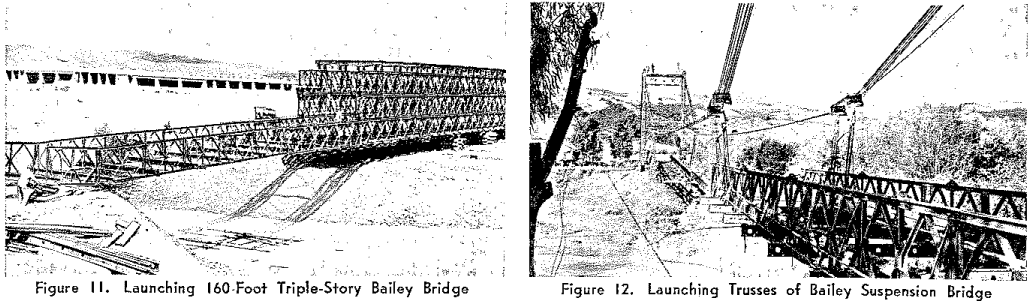
Launching methods. (Figures 11 and 12). The normal method of launching the assembled bridge on rollers by a skeleton launching nose is the fastest and simplest method for general use. However, for special uses and site conditions, many launching techniques are used. Power cranes not only make possible rapid assembly by units, but also erection of single girders by direct lift. At least 10 different methods of launching at restricted sites have been developed. The “Mesme” (Middle East School of Military Engineering) method uses a snubbed tank for both counterweight and launching power. Construction of floating bridges, multispan fixed bridges, and suspension bridges raises special launching problems. End-on erection, erection by single girders, launching by flotation, launching as a continuous bridge, and launching by high lines or suspension cables are some of the various solutions. The method used depends on the most convenient means of supporting the far end of the bridge, type of bridge, and character of the site.
The tactical employment of bridges
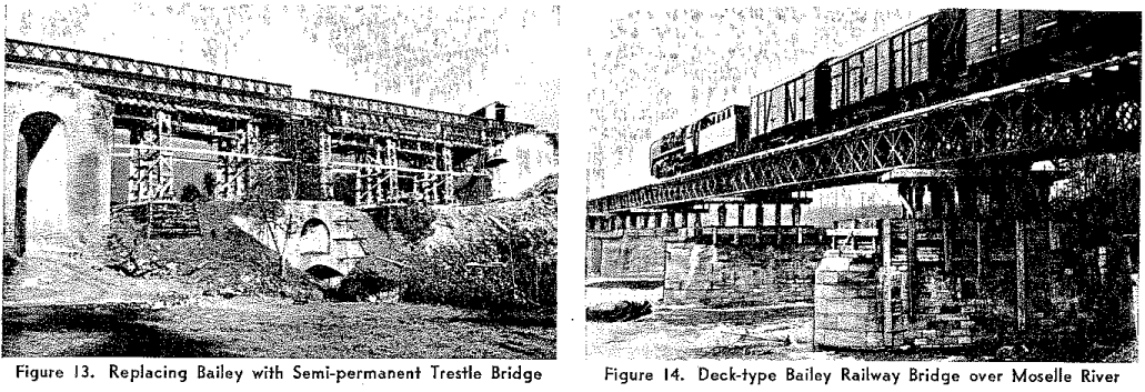
Tactical support bridging. The Bailey is designed primarily as a tactical support bridge to cross infantry, armor, and artillery in quantity after elimination of enemy small-arms and observed artillery fire from the site. Speed of erection is essential for tactical success. Equipment must be portable so it can be moved forward rapidly as the advance continues. The fixed Bailey is ideal for such use. It can be erected quickly at almost any type of site. While tanks roll across, a semi-permanent trestle bridge can be built underneath, ready to be opened in a matter of minutes by merely rolling back the Bailey. (Figure 13). The floating Bailey is regarded, however, as a semitactical bridge to replace the steel treadway bridge which can be built in less than half the time.
Tactical assault bridging. Because of its availability, speed of erection, and ease of repair and reinforcement, the fixed Bailey bridge has often been used as an assault bridge with the site still under light enemy fire. Although normal launching methods are generally used, the British have developed tank-mounted mobile assault bridges. (Some of these were described On p. 329 of The Military Engineer, August 1945).
Line of communications bridging. Bailey equipment has proved nearly as valuable for semipermanent bridges in the zone of communications as for tactical bridging. These bridges are mostly two-lane highway and single-track railway bridges. The latter were born of necessity in Italy when standard railway bridging failed to show up. Bailey railway bridges were later used extensively in France. (Figure 14). Deck-type construction with welded bracing is usually used. Other applications are in port construction and floating bridges. In the Normandy artificial harbors, Bailey spans were used for shore and pier-head connections. The floating Bailey on barges (Figure 15) thus proved to be the best type of floating semi-permanent bridge.


The use of Bailey Bridges in World War II
The Bailey bridge was used the world over from the Rhine to the Irrawaddy.
North Africa. In the North African campaign, little Bailey construction was required, although some valuable experience was gained. The British built their first triple-story bridges, one with an underslung lower story, and the other with floor at the bottom story and overhead bracing at the top story. An experimental suspension bridge was built at Zarialda, Algiers. (Figure 17).

Italy. In Italy, with its mountain gorges and swift rivers, more Bailey bridges were built than in any other theater. In twenty months over 3,000 fixed Baileys were erected by the Fifth and Eighth Armies—a total length of over 55 miles, the average bridge being about 100 feet long. Entirely new supply techniques were developed to handle the enormous movement of bridge equipment which rivaled the flow of ammunition. Standard unit truck loads of equipment which could be combined to build any type of structure were developed to simplify transportation and eliminate detailed bills of material. Specialized troop units were employed to transport, erect, remove, and replace Bailey bridges as the armies moved up the peninsula.
The Bailey was ideally suited to bridging the hundreds of demolished arches. (Figure 18). Early in the Italian campaign, the Germans frequently blew arches and left piers standing. This situation was made to order for the Bailey. Thus over the Sangro River, at the site of a brick arch bridge where the Germans had blown 19 spans but left 11 piers standing, the British erected a 1,126-foot Bailey, launching it as a continuous bridge. When the Germans began to blow piers too, the Bailey panel crib pier provided the answer and became a feature of nearly every long bridge in Italy. A 70-foot pier built in the Apennines by the Eighth Army is the highest on record. Where excessively high piers would have been required, the Bailey suspension bridge was available. A Bailey suspension bridge over the Volturno River at Triflisco carried 240,000 vehicles in eight months.
Most of the floating Bailey bridges were built over the Volturno and Po Rivers. Fifth Army built 12 floating Baileys in the Italian campaign. This compared to its 178 steel treadway bridges which were more suitable for the narrow mountain streams (average 110 feet). The British also experimented with mobile assault Bailey bridges and used one mounted on two tanks to cross the Rapido River.
Bailey line of communications bridges were built often as the campaign progressed. Frequently, two-lane deck-type construction was used. Most notable was the 1,370-foot two-lane deck-type Bailey on 13 pile piers over the Po River at Ostiglia built by the British in the final drive of late April 1945. (Figure 19). Its preassembled trusses were floated out on rafts and lifted into position by floating cranes. A shorter bridge of the same type at Pisa over the Arno River had two center Bailey spans with floor beams welded to the top of Bailey trusses which were launched complete on rollers. (Figure 20). Over the Arno at Florence, two 1,410-foot through-type continuous Bailey bridges were built side by side using pile piers surmounted by panel crib piers. Railway bridges were also built. The first was a through-type bridge at Cefalu, Sicily, which was decked to take both highway and railway traffic. Other bridges were built near Melfi and Foggia, Italy. These were multiple broken-span double-story through-type bridges with deck at the second story and bearings under the lower story.
Northwest Europe. In France and Germany, the Bailey bridge was the principal fixed tactical bridge for all armies, whereas the steel treadway and floating Bailey bridges were the principal floating bridges of the United States and British Armies, respectively. From the Normandy beaches inland, the fixed Bailey was carried and built side by side with the steel treadway bridge. Both bridges were often constructed under enemy fire. Speed was the keynote. Bridge equipment accompanied reconnaissance jeeps and construction frequently started before higher commanders even knew the infantry had crossed.
There were also technical developments. As in Italy, blown masonry arch bridges presented narrow piers and abutments. Where two bridges could not be placed side by side, the two-lane Bailey with its common center truss was used to cross the heavy traffic. Long continuous bridges on high panel crib piers, such as the Albert Canal bridge, presented new problems of erection. In that bridge, high lines and cranes were used to carry parts to the top of inaccessible piers. The triple-story bridges used in North Africa reappeared. Local barges were used to build the first floating Bailey Bridges on barges. The barges withstood crushing ice flows and supported long spans that passed debris and ice and could be converted into lift or bascule spans for river traffic. Deck-type Bailey railway bridges were developed for the mountain gorges of Southern France and supported the rapid advance up the Rhine.
The culmination of bridging in the European theater was the Rhine crossing. Although the British armies used the Bailey for fixed as well as floating bridges, the American armies made most use of the floating equipment in this crossing. The American armies built nine and the British seven floating Baileys. Both armies used British pontoons. (Figure 22). Average bridge length was well over 1,000 feet and average rate of erection about 90 feet per hour, one-half the rate for the U.S. 25-ton pontoon and steel treadway bridges. For this reason, floating Baileys were often used to replace the steel treadway bridges. Technical features of interest were Bailey panel fluke and crib-type anchors; special double landing bays for shore connections to provide for variations in water level of over 20 feet; naval craft used to move floating bridge sections into place; and local river barges instead of pontoons in several of the bridges. The largest bridge on barges was the 1,173-foot two-lane bridge built by the United States First Army at Bad Godesberg. (Figure 23). To build this bridge, 9 motorized cranes, 9 tugs, 4 sea mules, and 4 steamboats were used. During the first week it was open, the bridge crossed an average of 3,010 vehicles daily. The longest Bailey on record was a British semi-permanent fixed bridge over 5,000 feet long.
Far East. In the Far East, the Bailey bridge was not extensively used until the later phases of the war. On Guadalcanal several short spans were built, but Bailey construction was on a small scale in the Pacific area until the Philippine invasion. When the Japanese destroyed hundreds of bridges in their retreat from the islands, Bailey spans provided the answer. Construction was frequently under severe conditions due to scarcity of equipment, restricted sites, poor foundations, and flash floods. Examples of bridges that rivaled European bridges in size and technical accomplishment were the 410-foot continuous double-story Bailey on piers over the Bamban River and the 510-foot triple-story bridge with mid-story deck over the Bued River on Kennon Road, Luzon.
In Burma, the Bailey was used as a semi-permanent bridge at several points on the Ledo (or Stilwell) Road, but heavier equipment more suitable for such construction was generally preferred. Over the Schwel River, United States engineers built a standard British suspension bridge with 40-ton capacity and a 420-foot clear span, the longest of the war. (Figure 9). Over the Chindwin and Irrawaddy Rivers, the British constructed floating Baileys over 1,000 feet long.
The role of bridging
The Bailey bridge will profoundly affect future developments in military bridging. Although details of the ultimate military bridge cannot be predicted, certain trends can be foreseen as a result of experience with the Bailey.
Of first importance is the concept of an all-purpose bridge. The Bailey was a pioneer development in this respect, providing equipment adaptable for fixed, floating, and suspension bridges as well as for piers. However, it had a great number of parts—28 standard parts and over 100 special parts. Much simplification can be expected.
Load capacity and traffic requirements will soon make the Bailey obsolete. A trend to two-lane tactical bridging with a capacity range even greater than that of the Bailey appears inevitable. However, the Bailey principle of panel used to form multiple-story multiple-truss girders of variable length still governs.
The Bailey floor system is now obsolete. Although the Bailey design partly reduced the number of parts by joining stringers in frames, the tactical bridge of the future will provide both flooring and stringers in a single unit, probably in the form of deck balk or treadways.
The Bailey was designed wholly on the assumption that all erection would be by manpower. Mechanical power is no longer a chance luxury for engineers in a modern army. It is an essential weapon. Speed of erection essential in tactical bridging requires full use of such an available weapon. Accordingly, future designs can be expected to take account of new erection and launching techniques using mechanical power.
Originally the Bailey was designed only as a fixed bridge to carry heavy vehicles. Therefore, it is not surprising that performance in an unforeseen role was imperfect. Thus, whereas the Bailey fixed bridge was an ideal tactical bridge, the floating bridge was more properly a semi-permanent or quasi-tactical bridge, and Bailey assault and railway bridges were essentially expedients. The ultimate all-purpose bridge will satisfy requirements for all projected uses and thereby eliminate the need for special bridging to fill gaps which the standard bridge is unsuited to fill.
The Bailey bridge is not then the ultimate military bridge. Rather it is the pioneer, which more nearly than any other points the way to the ideal.

